Wednesday, June 29, 2011

Playing with Skeinforge


I ran into some user comments on reprap.org that stated the volume of plastic extruded per mm travelled did not change with W.O.T. This would mean that if you did two prints with the only variable changed being W.O.T that one of 1.1 would have a lot of extra plastic extruded compared to one of 1.9. So here are my results for exactly that:


The first photo shows the 1.1 and 1.9 W.O.T. prints side by side. It is obvious that the width of the plastic has changed, so I know that skeinforge is adjusting for my desired W.O.T. The 1.9 print shows a lot of blobs on the outer edge- this is because my perimeter flowrate ratio is higher than 1.0, done to compensate for a different W.O.T. A ratio may not be linear when changing the thickness like this...

The second photo shows a pereimeter of 1.3 and infill of 1.9 W.O.T. It is difficult to see in the photo, but the infill lines are not actually touching each other, implying that maybe skeinforge is usinge the extrude volume of 1.3 as a default across the whole print. I was hoping to print the perimeter on a fine W.O.T for accuracy and a high infill W.O.T for speed but I may need to rethink how I do this.

I will make some test prints next to see what effect changing the packing density variable has, I think I will end up homing in on a set of variables for working with one layer thickness, and have a subset of variables to change when I change W.O.T. I wish there was a way to save multiple profiles for printing PLA - I'll have to do some more searching.

Sunday, June 26, 2011

First usable part, and more improvements

Today I tried to print the modular spool hub again- this time with the heated bed.

I first changed some Skeinforge settings based on what I learned yesterday - mainly turning on comb, and increasing my perimeter flow rate over operating flowrate to 1.15 from 1.10. I noticed a couple of the perimeter layers of my minimug were not quite fully atached, so the perimeter adjustment should theoretically help that. I also upped my width over thickness ratio to 1.5 in both skeinforge and repsnapper to hopefully reduce the printing time.

Speaking of the minimug, it may have been watertight, but it definitely didn't hold alcohol. I'm guessing PLA is fairly hydrophobic. Good thing I decided to use some cheap rum instead of the good stuff. I'm thinking that my printer should be called Kraken in honor of that...

I was running into some issues with the X axis skipping steps on the first couple of tests, so I readjusted the trimpot a few times, and also adjusted the tension in the X belt. It had become a bit loose over time. On to the printing!

Excellent! I didn't have to fiddle with any other settings than the 2 W.O.T settings in Skeinforge and the corresponding values in Repsnapper and it still prints well! The heated bed worked really well to keep the part stuck down. I used a bed temp of 55 C, although since my thermistor is taped directly to the PCB instead of the top of the glass the actual temp was probably a bit lower. A few quick squirts from a can of compressed air cooled the part quickly and allowed it to pop right off the glass. Now back to the drawing board to design up some of the crazy ideas I've been having for new parts.

Edit: changing the repsnapper settings doesn't actually change anything. I'm thinking that by changing my W.O.T. to 1.5 reduced the apparent amount of extra plastic being extruded. I will print up some more test cubes later this week to see what else needs to be adjusted...

Saturday, June 25, 2011

Success!

I got some help on IRC yesterday with my issues of extruding too much plastic. It turns out there is a printer settings tab in repsnapper buried in the edit menu. This settings tab has info for layer height, width over thickness, and even an extruder multiplier. Once I changed these settings to match skeinforge everything fell into place. Here's a quick rundown of what I think are the important settings that is making this work for me:
Skeinforge:
  • layer height = 0.3
  • feed and flowrates = 25mm/s
  • width over thickness (both in carve and fill) = 1.3
  • filament diameter = 1.78 (measured directly with calipers)
  • Filament packing ratio = 1
Repsnapper:
  • layer height = 0.3
  • extruded material width = 0.39
  • multiplier = 1
I tried building a central disc of a filament spool holder and was having great success until it started lifting somewhere around halfway through. I should have known better than to try something that large (~80mm diameter) before getting my heated bed installed. But all the fill was looking beautiful and the holes were printing quite well.
I then tried printing my own version of the minimug since I figured it was about time to toast a successful printer. It came out quite nicely, although there are a lot of thin strings on the inside where the inner perimeter finished. I think I need to tweak with clip, and activate comb in skeinforge. There is also a vertical ridge along the side of the mug where the outer perimeter began each path. Despite all of this the mug is watertight, and I'll see if it holds scotch tonight. I'm thinking a mini shot of Laphroiag would make a great toast...


Friday, June 24, 2011

More calibration

I spent more time calibrating the settings today- I fine tuned the e_steps in firmware to give me a decent print, and then realized that my x and y step settings weren't yet right, making a 36.3 x 47.5 plate instead of 30 x 40. Doh. So I fixed the x and y steps, which screwed up the esteps again. I have read that esteps is supposed to be mm of filament INTO the extruder, and the same people have then said that in skeinforge you should set flowrate equal to feedrate. This results in WAY too much plastic being extruded. What settings besides esteps(firmware) and flowrate(skeinforge) control how much plastic is extruded?? Here is a shot of my before and after plates, with the esteps written in sharpie on them:

Mt current settings are 1000 for esteps, 25 for flowrate and feedrate, and a decent width over thickness ratio comes out at 1.3.

setting esteps for proper mm into the extruder is around 1406

Monday, June 20, 2011

Too hot...

I'd love to continue messing with skeinforge settings and printing more, but right now the temp in CA is about 90 F, which means my apartment is about 95 F, and the room with my printer setup is damn near 100 F. It's just too hot to be in there for more than 10 minutes without starting to sweat badly, and I don't want an errant bead of sweat to hit my RAMPS and fry it. I'll have to wait for the weekend when I can work in the morning before it gets too warm...

Sunday, June 19, 2011

Printer regression

Well I haven't been able to print anything today. I messed around with skeinforge settings too aggressively and now none of my prints work at all. I worked through a few iterations but my work room got too hot (95 F) to continue. I was having big problems with even getting the first layer to stick to the bed, and when it did the individual strands were not sticking together to create a cohesive layer. I think I've figured out why things went pear-shaped, but will wait until tomorrow to test my theories.

Process for printing

Here's the process I use to make a print. I had some trouble figuring it out from other blogs and the reprap wiki.

  1. Slice up an STL using skeinforge with the settings I want to try.
  2. Turn on the printer, move the head away from the bed and start heating the nozzle to 185C.
  3.  On the GCode tab of repsnapper, delete all but the first 3 lines of GCode from the box
  4. Load the skeinforge GCode
  5. Once the file is completely loaded, move the print head down so it is just barely above the glass bed.
  6. Move the head in X only to get it off the glass bed, test run the extruder to make sure everything is working, then move back to where we want the origin.
  7. Send a manual GCode G92 X0 Y0 Z0 E0 to set the origin
  8. Print!
I suppose I should just add the origin GCode to my skeinforge preface code, add that to the list of things to work on...

First prints

I got my machine to make a couple of prints last night - I still can't believe I was able to get the settings roughed in well enough to make usable prints this quickly. I made a simple 10mm thick calibration plate with holes to test out the various functions. Right now I have my e_steps_per_unit = 250 in the firmware. I think this is probably a bit high, but am not really sure what other Makergear plastruders are set to. With it set to 250, it takes six clicks of extrude to push 10mm of filament into the extruder. So that should be 250*6/10 = 150 to reach the appropriate value. I'll try that later today and see how it works. I'm kind of confused at the length slider in repsnapper - does 10 mean it will push 10 mm into the extruder, or 10 mm is supposed to come out of the nozzle?
For the plate I set skeinforge dimensions to filament diameter =  1.78 , packing density ratio = 1, retract speed = 14mm/s, distance 5mm, extra restart of 0.1mm.
For skeinforge speed I used feedrate=20, flowrate=180


The bottom shows that it is probably squirting too much plastic, so I adjusted the flowrate down to 140 for the disc print. Overall it looks pretty good to me! The circle is round, the lines straight, and it didn't lift any strings while depositing. Here's the second print, the beginning of a giant glass (I'm not used to thinking in mm while designing parts so I made a shotglass 1.5 inches wide at the base and nearly 3 inches tall!!). I stopped it before it even reached the bottom of the inside of the glass since I could see it wasn't quite working out.


Saturday, June 18, 2011

Major build complete - beginning testing

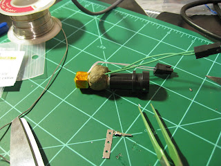
I finished wiring up the X-axis this morning, man do I hate working with this shielded cable. It has a tight weave of metal strips similar to chinese fingercuffs. The wiring underneath that has some sort of indestructible insulation which doesn't work with wire strippers so I had to use an exacto knife to slice off enough to attach connectors. A real pain that took about 40 minutes per cable:

I then wired up the hot end so I could cure the ceramic adhesive I applied yesterday. I found that repsnapper will continue to drive the heater even after you turn it off if there is no thermistor connected!!! Good thing I was monitoring the output with a DVM. I then built the hot end, installed the thermistor and got it all mounted and tested the extruder.


I have spent about 4 hours now dinking with skeinforge settings and attempting to print without destroying the machine, since I still haven't installed the endstops. Its been a lot of reading f the G-Code wiki and skeinforge documents. I'll upload some pics once I have something I can actually photograph.

Friday, June 17, 2011

Y-Axis is alive!

I spent the afternoon modding the ATX power supply to turn on without a motherboard, soldering up the stepper drivers and opto-endstops, uploading the Sprinter firmware to the Mega 2560, and wiring a shielded cable for the Y-axis. I had to tinker with the configuration file a bit to turn off the endstops for now- I don't have any plugged in so repsnapper refused to move motors without them. But once I got the settings right the Y-axis started responding to the simple move commands in repsnapper!

I've been using an old Hako 927 soldering iron for all of the electronics - and also for all of the crimped connectors for the wiring into the RAMPS. It was a reject from work, but has settable temperature control and can be set up with a ground for ESD electronics soldering. It's probably 20 years old but still works like a champ.

I add a bit of solder after I crimp on the connectors before I insert them into the connector housing. I have had trouble in the past with crimped connectors working loose and creating intermittent shorts- a real pain in the ass to troubleshoot. The list of things to work on is starting to get shorter, and I haven't run into any major snags so far...
To do: wire up Z-axis, wire up X-axis, finish hot end, install and wire extruder, install print bed, install and wire endstops.

Chassis finished, RAMPS soldering fun

I finished up the chassis build this morning by installing the X-axis motor and belt, and tuning everything up one more time. All axes seem to move with very little effort- the motors seem to add more resistance than the slides so I 'think' I'm ok.
I also worked on the Makergear hot end- soldering the teflon coated wires and adding the last of the ceramic adhesive. My final nichrome resistance is about 6.3 ohms, so that should be roughly 2 amps supplied at 12 volts.
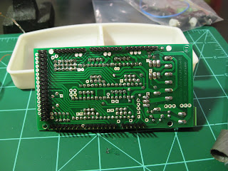
I also soldered up the RAMPS 1.2 board. Makergear shipped me the ultimachine V1.2 package. I would rather have had 1.3 but I'm just being picky. Before and after shots:


I still have to solder the stepper driver boards and opto-endstops, then I'll start experimenting with uploading the Sprinter firmware to the arduino and see if I can keep the magic smoke inside all the chips.

Wednesday, June 15, 2011

X-axis and cold extruder build

I continued with building the X-axis and the extruder drive mechanism. The X-axis blocks have about 10 captured M3 nuts- insanely difficult to install and align. I got them all in but it looks like I stressed some of the plastic on one of them a little too much while tightening the axis rod. I'll add pictures tomorrow. The extruder drive went together cleanly- I was glad of the note to install one of the captured M4 nuts before installing the geared stepper. Looks like I will work on the X-Z axis interface tomorrow and start building the hot end. Hopefully I'll be soldering up the RAMPS over the weekend and get some first motion next week.

Building the frame and Y-axis

So I finally got down to business today and started the mechanical assembly. Assembling the frame and Y-axis took about 2.5 hours, give or take. I used the Prusa build instructions [here] while cross referencing the Makergear specific changes [here]. So far things have gone pretty smoothly. Getting the Y-axis to slide smoothly took a little coaxing- a lot of wiggling f the linear rods and fine tuning of the bar clamps on the ends. I think it is smooth enough to run well, but overall it is a bit finicky.


Finding all the proper hardware to assemble the Y-axis took a while- there was a plastic bag of miscellaneous bolts, washers and nuts which had the right sizes to make things work. I ended up getting out the calipers to verify that I had the right M3x12 bolts for the wooden frame. Also- the 3rd bolt that holds the Y-axis motor to its bracket would not fit in the space next to the idler wheel. For now I'm going without it, I'll kludge a solution if I determine I really need the extra strength.

Tuesday, June 14, 2011

Playing with Skeinforge

I spent some time today building a 3d model of a calibration plate for testing my printer, and decided to do some reading up on Skeinforge settings [Skeinforge FAQ]. The FAQ is actually pretty laid out with what the different settings do with example photos of many of the changes in settings. So here is a screenshot of one of the solid layers showing the beginning. I am designing some relatively shallow calibration parts to allow for quick printing and changing of settings while I learn how to print well.

Sunday, June 12, 2011

Parts are here!

My kit arrived yesterday with everything except the heated bed. I can't wait to dive in but I have other priorities until later this week. For now I have just opened the box and pulled out some of the RP parts to inspect.

The quality is very good. One of my friends has offered to help solder up the RAMPS electronics in return for being able to use the machine for some of his project ideas. Overall this should get everything up and running a little quicker. I'll post later this week once I get my workbench cleared and start digging into everything.

Wednesday, June 1, 2011

Making keys with a Reprap

This guy has figured out how to make a parametric key printer, just type in the pin code and out pops a plastic key. It reminds me of the "credit card keys" AAA used to give out for getting into your car. Probably not good for long term use but great in a pinch.

eclecticc

Monday, May 30, 2011

Waiting...

Waiting is the hardest part. I've been in contact with Makergear, and my kit is being prepared for shipment but will probably take another week or two before it gets into my hands. Oh well, I've been passing the time reading up on the various software packages. I've been looking into firmware packages for the RAMPS controller and think that the Sprinter firmware looks pretty promising. I think it can be driven by Repsnapper, one more thing to track down.

I also dug up the Solidworks model of the Prusa Mendel. It's really useful to be able to rotate the model around and see exactly how the different parts fit together. It is especially good for the extruder parts.

Sunday, May 22, 2011

Software

Here is the process for creating new parts to print as I see it
(this was longer but I lost it due to a restart forced by the installation of Deamon tools-boo)
1. Create a 3d model using a CAD program (Solidworks, openscad, AoI, google sktchup, etc)
2. Export the 3d model as an STL file.
3. Skein (skane), the STL using a program like skeinforge or repsnapper to create the G-Code that will drive the printer

4. Load the G-Code to the printer using Repsnapper and print away

It seems like most of the parameters for controlling the quality of the print are managed through the skeining software.

Parts ordered!

I've been waiting for Maker Faire to get some more experience with 3d printers and talk to people that make and use them. Today was the last thing I was waiting for to bite the bullet and actually dive into this hobby.

I bought my kit from Makergear.com and we'll see how long it takes to get here, estimate is 2-3 weeks currently.

Maker Faire

Went to Maker Faire today to check out some of the reprap projects on display. Found a lot of cool stuff going on, and managed to see examples of Makerbots, Fab@Home, Rapman, and countless Mendels and Huxleys. I was totally impressed with the quality of the printed parts on display.
 Lasercut kit from <techzomecom.com>
Printed Huxley from techzone

Friday, May 20, 2011

Hello world...

Here goes nothing! I am planning on building a Prusa Mendel Reprap and will use this blog to document my progress and hopefully help others avoid the same mistakes that I make.